Correctly designing aluminum die castings poses many challenges. Even the smallest design detail can have a huge impact on the casting operation. Therefore, every detail should be carefully designed according to the guiding principles recommended in this article.
Here we focus on several main considerations in the structural design of aluminum die castings, as well as the recommended precision of each factor you should be following during product design.
1. Material Selection
Product design can vary significantly depending on your material choice. Each alloy will have some limitations. Careful design and execution are needed to achieve the best integrity and strength of aluminum die castings.
Depending on the metal elements used with aluminum, the characteristics of the alloy such as weight, fluidity, strength, conductivity, melting point etc. will vary. However, not all alloys are suitable for die casting.
Some common aluminum alloys that you can use for die casting include:
- A380
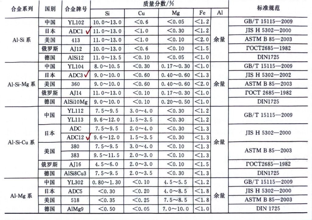
- A383 (ADC12)
- A413
There are also many other aluminum alloys to choose from. The right aluminum alloy needs to be selected based on your requirements and budget constraints.
Chemical Composition Table of International Main Aluminum Die Casting Alloys
2. Draft
Draft is one of the most important parameters for aluminum die casting. It provides a taper or inclination for the core and surface of the part perpendicular to the mold parting surface.
Designers must provide sufficient draft angle where needed. Without sufficient draft angle, the casting will be difficult to eject after solidification, and there is a risk of damaging the part or even the mold itself.
When calculating the draft angle, please consider the following factors:
- Usually, most geometric features adopt common draft angles.
- For inner walls and surfaces, the draft angle is typically twice as large as that for outer walls.
- Draft angle requirements may also vary depending on the alloy material. You need to calculate the draft angle based on your choice of aluminum alloy.
Casting Draft Corresponding to Different Wall Depths
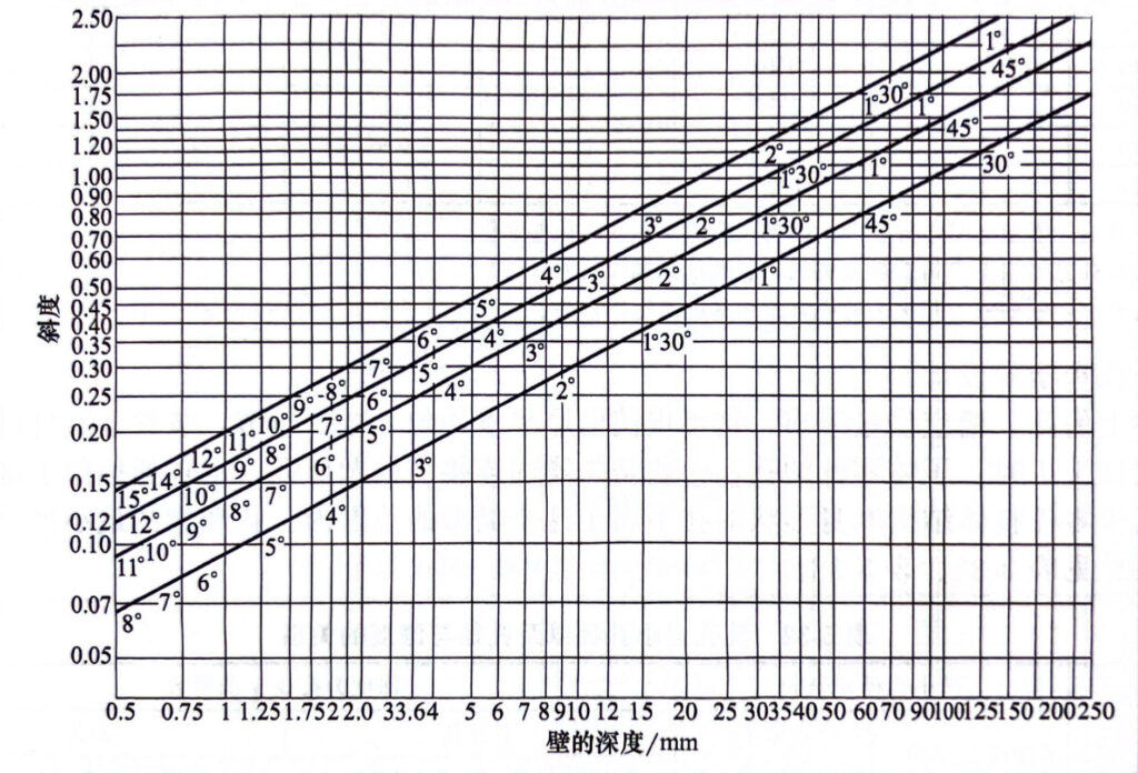
If you want to achieve a smaller draft angle, precision tolerances can be used. However, they will involve more precise machining and higher costs. Therefore, it is recommended to avoid using precision tolerances unless necessary.
3. Moving Die & Fixed Die
It is crucial to consider the match between the moving die and the fixed die during the design process. Problems with any of these components can hinder the aluminum die casting process. The design of the moving die typically faces more challenges and has more components to consider, while the construction of the fixed die is relatively simpler. When material is injected into the mold, the core may slide out due to the pressure generated by excess material, resulting in over-sized castings. This needs to be noted.
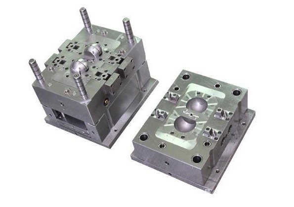
Moving Die and Fixed Die
The tolerance of the moving die component is a function of Linear Tolerance and Projected Area Tolerance. The linear tolerance here refers to the length of the core slider, while the projected area is the top of the core slider facing the molten material.
The shifting can occur in a linear direction perpendicular to the projected area. Therefore, ideally, the tolerance of the moving die component should be maintained at a minimum value of zero.
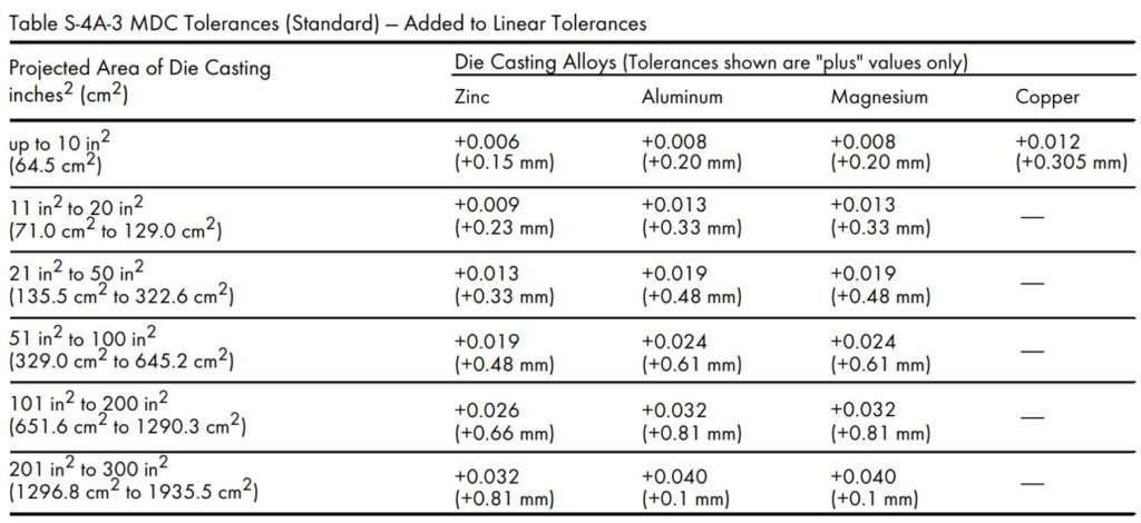
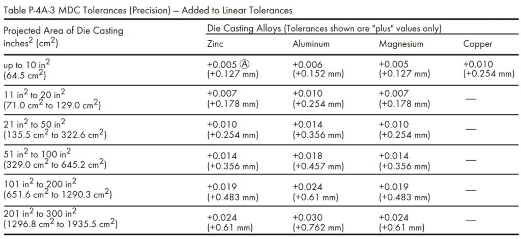
Due to the construction of the die casting equipment, only larger or positive tolerances can be achieved during the machining process. According to the NADCA guidelines, the following show the standard tolerances and precision tolerances for some variable projected areas.
4. Parting Line
The parting line is the location where the two halves of the mold meet and combine to form the complete product structure. The parting line is a fundamental feature of the die casting process and is unavoidable due to the fact that the product design consists of at least two parts.
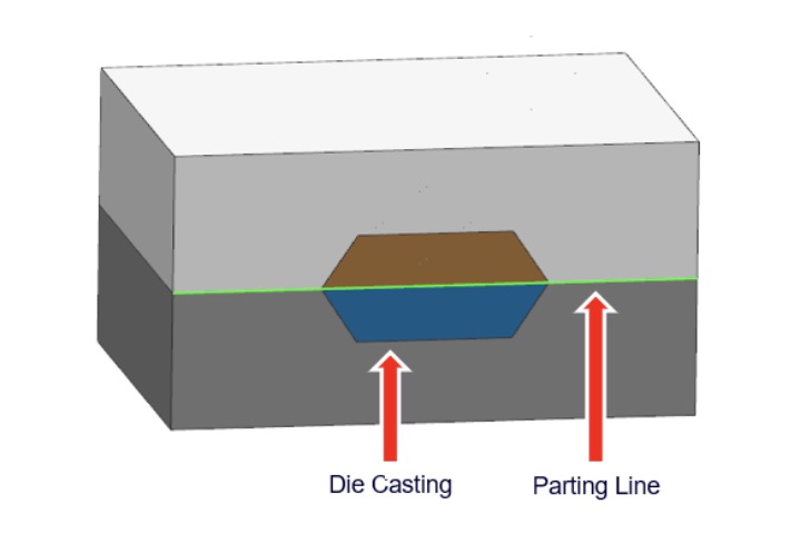
The parting line is a clear boundary between the moving and fixed parts of the mold, serving to distinguish between the two. The parting line tolerance refers to the maximum allowable amount of mold separation to ensure the correct execution of the aluminum die casting process.
When the material pressure attempts to separate the two halves of the mold, material can flow out from the separation created at the parting line. This is known as a flash defect in die casting. The cast component requires an additional trimming process to remove the flash, runner, gates, and overflow.
The parting line tolerance is a function of the projected area of the mold, representing the separation surface where molten material moves from one mold half to another.
There is zero separation between the two halves of a completely enclosed mold, so the projected area tolerance always has a positive value. The extent of mold separation depends on the die casting pressure and the extent of clamping force used to keep the two halves of the mold together.
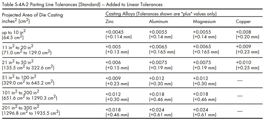
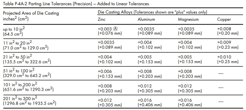
Parting line tolerances may vary depending on the alloy, size, and depth of the parts. Below are the recommended standard and precision tolerances for mold casting parting lines. However, if the projected area of the die casting exceeds 300 in2 (1935.5 cm2), please consult with your die casting supplier.
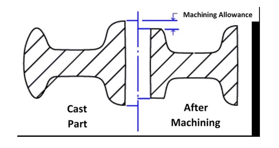
5. Machining Allowance
Machining allowance refers to the amount of raw material that can be removed from a completed aluminum die casting. There may be some roughness on the surface of the die casting, and there may be some deviations from the actual design in terms of geometry. Therefore, after the die casting process, secondary machining is required to correct these errors.
The optimal mechanical properties and density of castings are typically located at or near their surfaces. This means that during the machining process, excessive material removal should be avoided to prevent compromising these properties. Therefore, the machining allowance should be carefully determined to ensure that it does not penetrate lower-density sections. Removing too much material can lead to defects in the product.
During the design phase, it is crucial to specify a certain machining allowance for machining and casting variables. Too little machining allowance may not meet surface quality requirements and may lead to defects in the part. Conversely, an excessively large machining allowance can increase production time, labor, and costs. Therefore, determining the appropriate machining allowance is crucial. Communicating early with the die casting supplier can help you determine the suitable machining allowance. We can provide recommendations based on your requirements and the characteristics of the casting process.
Generally, a recommended minimum machining allowance of 0.2mm is advised to reduce tool wear and minimize porosity in the casting. The maximum machining allowance is the sum of this minimum value and the casting deformation. This means that when determining the machining allowance, the potential deformation during the casting process also needs to be considered.
However, for flat and larger components, additional considerations are required. In such cases, you can consult with your die casting supplier to ensure the machining allowance value.
Machining Allowance

6. Wall Thickness
In product design, uniform wall thickness should be maintained. Metal needs to flow uniformly during the casting process to fill every part of the mold. Uneven wall thickness can obstruct metal flow, resulting in insufficient filling of certain areas. Additionally, uniform wall thickness also aids in the uniform cooling and solidification of the metal, leading to higher-quality castings. Therefore, maintaining uniform wall thickness can significantly improve the quality and integrity of castings.
If, for certain design considerations, it is necessary to alter the wall thickness of a casting, it should be done gradually through the introduction of rounded corners or radii instead of sudden thickness changes. This helps avoid sharp edges in the design.
Sharp edges should be avoided in product design as they can affect metal flow and cause difficulties in mold release after casting. However, if walls meet at a parting line, you can keep the edges as they are. This is because minor variations in wall thickness typically do not have a significant impact on metal flow or mold release in these areas.
In aluminum die-casting design, there is no fixed standard for wall thickness, but it is generally recommended to keep the wall thickness within a reasonable range. The typical wall thickness for aluminum die-castings ranges from 2.0mm to 3.5mm.
However, wall thickness is also influenced by factors such as alloy type, part configuration, part size, and die-casting application. For example, if the die-casting is of a small size, the wall thickness can be reduced accordingly, even to as thin as 0.7mm.
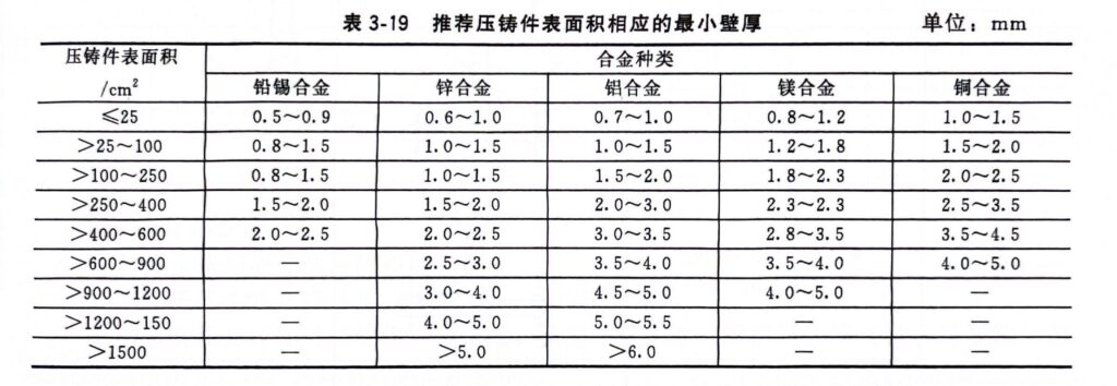
The Recommend Minimum Wall Thickness Corresponding to The Surface Area of The Die Cast Part
For both small and large aluminum die-castings, there may be some special situations or requirements that make their wall thicknesses exceed the usual maximum and minimum limits. If you encounter difficulties with wall thickness issues for aluminum die cast parts, you can consult your die casting supplier.
Thicker wall thicknesses can increase the stiffness of the part. However, if they are too thick, they can extend the cooling time, hindering the solidification process. This may result in poor casting quality unless appropriate measures are taken.
Thick walls can also add extra weight to the product. Therefore, product designers who focus on making parts lighter prefer thin walls. However, if the walls are made too thin, exceeding a certain limit, the stiffness will be too low, and the part may be prone to deformation during further processing.
Deformation issues can be addressed through stepped machining. However, thin walls in castings lack stiffness and strength. Providing reinforcing ribs can significantly improve the stiffness of thin walls, making them more stable.
Of course, modern diecasting technology is advanced enough to handle most critical design parameters. However, you should still consider wall thickness issues if they have an impact on the performance or cost of your part.
7. Lightweight Design
Metal Savers and Pockets are two common features of lightweight design. These features can significantly reduce the amount of material required to produce components without compromising their integrity and strength.
Metal savers typically involves creating hollow spaces within the ribs to reduce the amount of material used, thus making the component lighter. The sections between the ribs do not serve a significant purpose and can safely be removed from the design.
When designing a metal saver for aluminum die-castings, you should keep the following points in mind:
- Avoid sharp edges along with the metal saver. Sharp edges can lead to stress concentration, increasing the risk of fracture. Therefore, it is recommended to use rounded corners or radii, and this radius should be as large as possible. Consider a minimum radius of 0.06 inch (1.524 mm).
- Maintain uniform wall thickness around ribs: Uniform wall thickness helps ensure strength and durability of the ribs in various sections. Try to keep this thickness close to the typically recommended values.
- Provide as large a draft angle as possible.
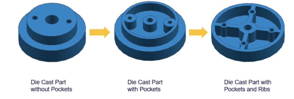
Pockets are another technique to reduce material weight. Thicker sections with holes can be replaced with thin-walled sections to reduce the amount of material needed for production. However, pockets can sometimes lead to irregular shrinkage. Therefore, designers need to carefully decide where to use pockets.
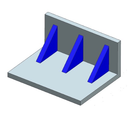
To enhance the structural strength of the pockets, you can add ribs around them. Ribs can increase the stiffness of the pockets and help the metal flow better during the manufacturing process. Additionally, reducing the amount of metal used can increase the cooling speed, which helps to shorten the overall production cycle.
The following diagram demonstrates the effect of pockets with and without ribs in a part: