The rationality of the structure and process adaptability of die-casting parts are critical factors determining the smooth progress of subsequent work. For example, the design of fillets and radii, mastery of shrinkage laws, the arrangement of ejection mechanisms, the types and severity of defects, and more, all depend on the quality of the die-casting process itself.
Fillets & Radii
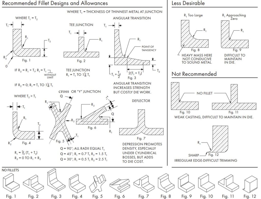
Contrary to popular belief, fillets and radii are not the same thing. Although both refer to rounded edges in the design of aluminum die-casting parts, the internal rounded edges are called fillets, while the external rounded edges are called radii.
Radii and fillets are extremely important features for any aluminum die-casting part design. They can significantly reduce turbulence generated during the metal injection process, ensuring smoother metal flow. Therefore, parts can achieve better structural integrity.
Here are some design suggestions for radii/fillets:
- Sharp corners where two intersecting surfaces meet should be connected using radii/fillets. This can prevent high stress concentration at that part of the mold or component.
- Edges or corners along the mold parting line do not require radii/fillets.
- Provide sufficient draft angle for fillets perpendicular to the parting line.
You can follow these guidelines to design radii/fillets in your components.
Shrinkage
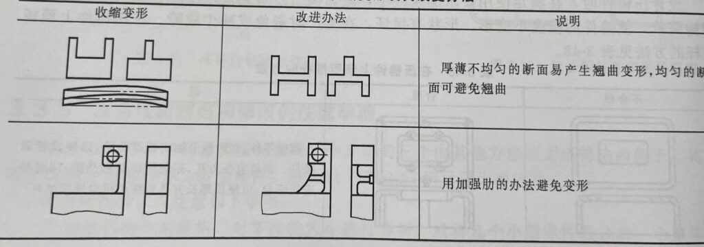
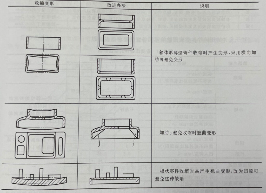
Shrinkage is a very common and inevitable phenomenon in aluminum die-casting. Any metal alloy will shrink to some extent when the molten metal begins to cool and solidify. Therefore, designers must make necessary adjustments to the product design to allow for shrinkage.
Thicker sections are prone to shrinkage, leading to the formation of internal pores. Local overheating can also cause shrinkage, resulting in pores. These areas need to be locally cooled by improving mold design. However, this may increase the casting cycle time.
Designers should consider the following factors when designing to reduce shrinkage in aluminum die-castings:
- Avoid using large/thick sections in the design. If possible, redesign using thinner sections and metal-saving cores.
- Add flat or vertical ribs can improve the feeding characteristics and reduce the tendency for shrinkage.
- Add squeeze pins can reduce the shrinkage porosity in the localized area.
Boss
Bosses are necessary for parts that need to be mounted in other positions. They serve as stand-offs and mounting points. However, improper design and positioning of bosses can lead to manufacturing difficulties, thus increasing costs.
Bosses can also increase material requirements and the weight of aluminum casting. In order to obtain lighter parts, bosses can be redesigned in the following ways.
In a part design, some factors you should consider for bosses design:
- If a hole needs to be added in the center of the boss, try to maintain uniform wall thickness.
- Provide a larger fillet for the boss so that molten metal can flow smoothly into it.
- Ribs are recommended because they can help the boss fill fully and also provide extra strength for the boss.
- Provide sufficient draft angle for the boss to make it easier for the casting to be demolded.
Side Cores/ Slides
Any holes and undercuts parallel to the parting line in the design will greatly increase the complexity of aluminum die casting, and even make it impossible to cast through conventional means. The introduction of side cores/slides can easily manufacture parts with holes and undercuts.
Cores are used to form holes in a part, while slides are used in the design with undercuts. However, they significantly increase the cost to die construction. Since cores and slides are pulled out separately from half of the main mold, they have a great impact on the casting cycle of parts.
The use of slides within a die may also lead to the offset of parting lines. This is due to the force applied by the mechanical lock to keep the slide in position during the casting process. This situation is more common in unit dies.
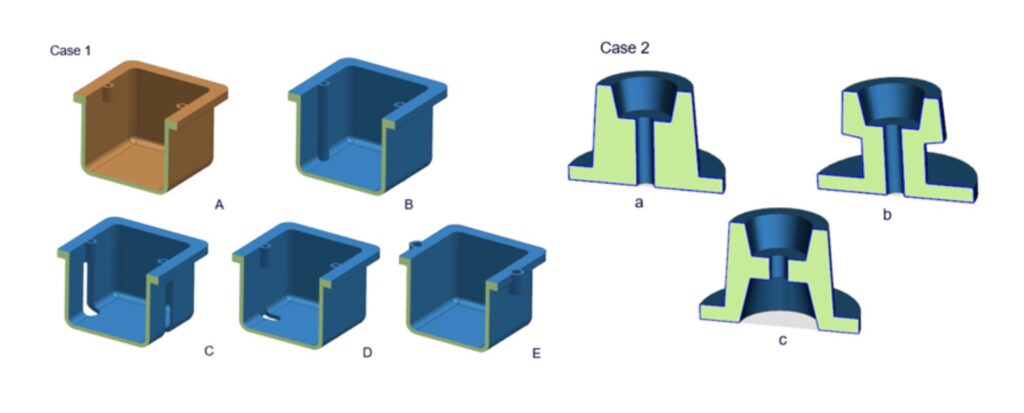
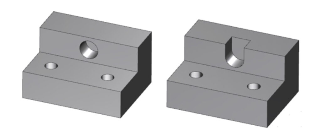
Designers should try to make such geometric features parallel to the pulling direction of the mold, or redesign the part to eliminate the need for cores/slides. Here is an example that demonstrates how to redesign a part to eliminate the need for side cores.
However, in some cases, you must introduce cores/slides to cast a feature that does not require machining later. You can design core slides or pulls to reduce the need for most or all secondary machining operation.
In this way, the difficulties brought by the increased tooling cost and slower casting cycle at the beginning are compensated by reducing secondary maching operations. This method also greatly extends the reuse rate of parts.
The working mechanism of side cores/slides is that the pulling of side cores and the movement of slides are usually driven by angle pins or hydraulic cylinders. The angle pin is a mechanical mean for the movement of cores/slides. The opening and closing sequence of the main die can activate it.
Therefore, angle pins do not require an additional power source to function and are an economical means of production. However, angle pins can interfere with the removal of castings and are only suitable for a shorter slide.
Top slides are also difficult to use with angle pins and can only be achieved through springs. The use of hydraulic methods can solve these problems. You can choose and define the cycle yourself and use the top slide with it. This will not interfere with the recovery of castings.
There are other methods available for core/slide movement. Designers must choose the appropriate method by analyzing the budget, production volume, part size, length of core/slide travel into the casting, etc.
You can discuss with your die casting manufacturer to obtain appropriate suggestions on designing the side core pull/slide mechanism. Welcome to consult DAYE Diecasting, and we will be happy to help you.
Undercut
Undercut usually refers to a recessed geometric feature or surface of a part that cannot be processed with a straight cutting tool. In the case of die casting, undercut refers to the feature that restrict the ejection of the casting with a single pull mechanism.
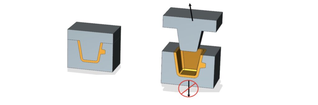
Therefore, when designing a part, you must consider the potential difficulties that may arise during tooling and casting in advance. Sometimes, you can eliminate the influence of the undercut by cleverly selecting the orientation of the aluminum die casting. Without the use of side cores, it is impossible to eliminate the influence of the undercut in most cases.
However, adding side cores to the design will complicate the mold manufacturing and casting process, resulting in higher costs and longer installation time than traditional aluminum die casting.
So, when designing the undercut, you should keep the following important points in mind:
- Discuss with your manufacturer to see if he can use special cutting tools such as T-shaped or V-shaped tools that can reach inaccessible places.
- Keep the number of external undercuts to a minimum because they require side cores, which will increase tooling costs.
- Adjust the parting line can solve some undercuts.
- Redesign your parts to eliminate internal undercuts.
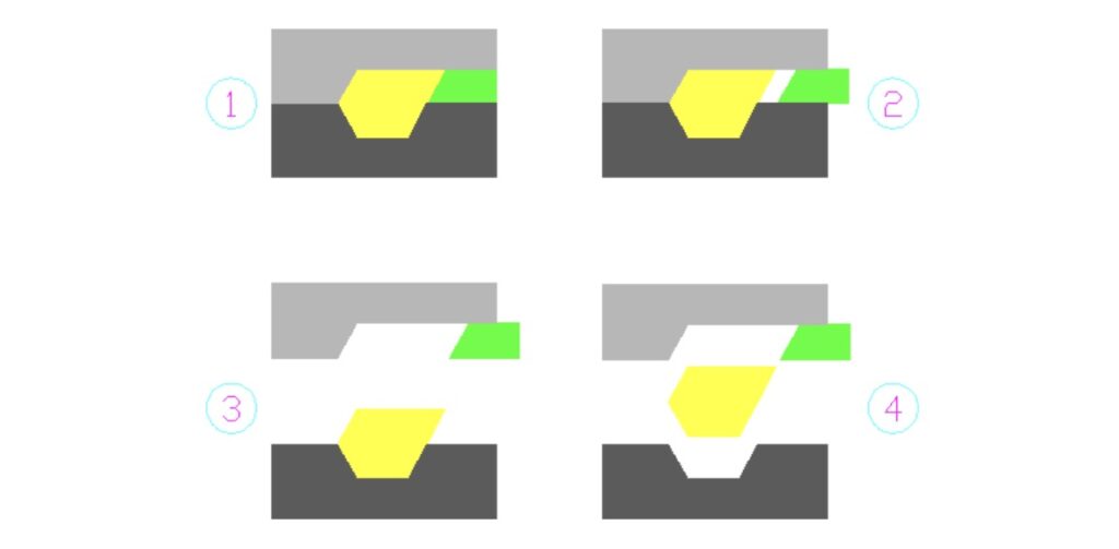
- Avoid undercuts that are not facing the die pull direction. They cannot be ejected without placing side cores.
- Undercuts beneath bosses can hinder the ejection of the aluminum casting.
If possible, it is best to avoid any type of undercuts in the design.
Ejector design
Due to solidification shrinkage, the solidified aluminum casting tends to clamp into the die. To ensure the removal of the aluminum casting, some ejector components need to apply additional force inside the die.
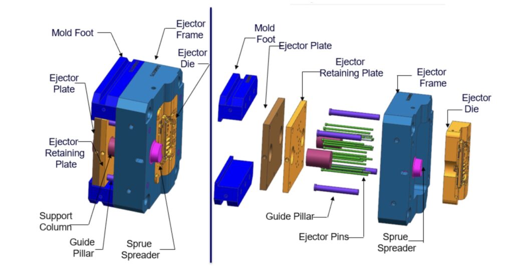
The ejector machine of the die-casting equipment can include multiple components. A die-casting mold mainly consists of two parts, namely the cover die half and the ejector die half. The ejector mechanism is placed in the ejector die.
The parting line is the separation point between the two die halves. After casting is completed, the ejector die separates relative to the parting line. However, there are more complex devices with multiple die settings, which makes the ejection system more intricate.
Here, we will only discuss the traditional two-part die, as it is more common and cost-effective. In this type of die, the ejector section includes the ejector pin, ejector plate, inserts, runners, and any engraved parts present in the design.
The ejection mechanism mainly depends on two components of the die: ejector pins and ejector plate.
Ejector Pins
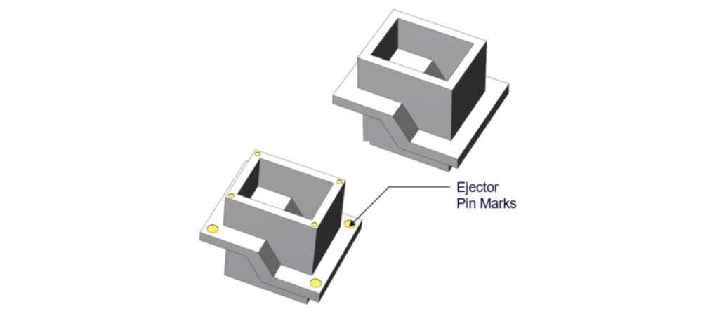
Ejector pins push the solidified casting out of the die. Another function of ejector pins is to clamp the casting so that it does not bend due to stress concentration during solidification. However, the drawback is that they will leave marks on the casting.
Therefore, designers should carefully consider the size, configuration, and other aspects of the casting when selecting the location and size of ejector pins. When designing ejector pins, you should follow the following guidelines:
- Place ejector pins in a non-functional area of the casting, such as the bottom of deep pockets, overflow, on a boss, or the bottom of ribs, etc.
- Ejector pins will leave marks when ejecting the casting. Therefore, do not face the appearance surface of the casting towards the ejector pins.
- The recommended tolerance for raised or recessed pin marks is .015” (.381 mm).
- Pay attention to the suggestions of the die-casting manufacturer, who can help you choose better ejector pin sizes, locations, and quantities.
Appropriate toolmaking methods can greatly reduce the marks left by ejectors. However, these marks cannot be completely eliminated. OEM manufacturers and die-casting manufacturers should reach a consensus on the location of ejector pins.
It should also be noted that ejector pins can also form a flash around them. Unless the customer rejects it, it is usually not processed. The pin flashes can be crushed and flattened to minimize their footprint.
Ejector Plate
The ejector plate can either serve as a supplementary component for ejector pins or work independently. Typically, die-casting workers use the ejector plate as the mounting surface for ejector pins. Since pressure is only applied to the ejector plate, it simultaneously pushes the ejector pins forward to eject the casting.
The ejector plate can also work independently without ejector pins. However, this scenario is usually only seen in small-scale die-casting. The part is ejected through the force applied by the plate. In a sense, compared to ejector pins, the ejector plate leaves no marks on the casting like ejector pins.
Pressure Tightness
The pressure tightness is a measure of the integrity of aluminum die castings, that indicate their ability to withstand a certain fluid pressure. In some cases, purchasers may require castings to have specified pressure tightness.
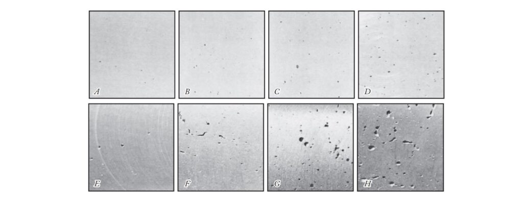
Pressure tightness largely depends on density and porosity. Even a small amount of porosity can affect the pressure tightness of the part and cause leakage during application. Many factors can affect the density and porosity of aluminum castings.
Entrapped air inside the aluminum die casting mold is a major problem for any manufacturer. When molten metal is injected under high pressure, resistance caused by trapped air can create porosity. The presence of pores in castings also reduces their density, thereby reducing structural integrity.
There are many factors that can lead to the formation of pores, making it very difficult to obtain completely pore-free castings. Effective DFM (Design for Manufacturing) and good quality control throughout the process can achieve appropriate density and minimal porosity.
Designers should consider the following design parameters to obtain the best pressure tightness for aluminum die castings:
- Carefully follow the design guidelines related to fillets, ribs, and corners. Otherwise, metal flow will not be smooth, and turbulence will lead to the formation of pores.
- Try to maintain uniform wall thickness to promote smooth metal flow. Avoid heavy sections and sudden changes in thickness.
- Holes that must maintain pressure tightness should be cored rather than machining to minimize the impact of porosity.
- Provide sufficient draft for all holes and passages that will not undergo post-machining. However, if the cored holes require machining after casting, provide a minimal draft.
- Simulating the entire aluminum die casting process will help you identify potential issues ahead of time. Run a mold flow analysis to identify features in the mold that can improve casting quality.
- Vacuum-assisted die casting equipment can significantly reduce porosity in aluminum die castings. Therefore, the parts have fewer defects and better density characteristics.
Secondary Machining Operations
Secondary machining can also affect the pressure tightness of aluminum die castings. You should adopt the following machining guidelines:
- The densest part of the casting is located on or close to its surface. The interior is usually less dense with more pores. Therefore, the minimum machining allowance should be specified to avoid exposing the porous interior of the casting.
- If the machining allowance required for the part exceeds the allowable range, it may expose the porous interior. Therefore, to achieve the best pressure tightness, post-hole filling may be required.
- Avoid machining both sides of the casting that requires pressure sealing.
- Avoid using large draft where extensive machining will be done. Especially provide minimum draft for core holes.
Apart from the above considerations, the selection of alloy materials also plays a crucial role in ensuring the pressure tightness of aluminum castings. In some cases, certain alloys achieve better results in enhancing the pressure tightness of aluminum components.
A range of testing equipment can be utilized to measure the pressure tightness of aluminum components. Typically, pressure tightness tests are conducted within a pressure range of 5 to 40 psi. If higher pressure tightness is required, designers should engage in discussions with die casting manufacturers.
Part Strength
The strength requirements for aluminum components will have a significant impact on overall production costs and time. Therefore, you can clearly discuss the strength requirements of the components with the die casting manufacturer to select a feasible aluminum die casting design method.
The strength of aluminum die-cast components depends on many factors. Below, we provide some suggestions on ensuring the strength of die-cast components:
- First, start by selecting the appropriate aluminum alloy. The alloy used for production will have a significant impact on the strength of the component. However, mechanical strength is not the only key parameter here. The selected alloy must have sufficient machinability and meet other conditions.
- Cast more features in-situ as much as possible. Machining any features later will create machining stress on the aluminum component.
- Use vacuum-assisted aluminum die-casting processes to reduce pores in the component. This will increase the density of the component, thereby improving its structural integrity and strength.
- You should use rounded corners to increase the rigidity of the component.
Following these guidelines can help you increase the strength of die-cast components. However, you also need to consider many other minor factors. Discuss with your die casting manufacturer for suggestions on increasing component strength.
Tiny Features
Tiny features require more advanced cutting tools for processing. The time, cost and difficulty of processing tools for tiny features are much greater. Features with standard tolerances can be achieved at a relatively low cost and are precise enough for any regular consumer.
However, if your components have very advanced applications, you may need to process them with precise tolerances. However, precision machining beyond a certain limit is called micromachining, which cannot be achieved with standard machining tools.
Micromachining deals with processing features with tolerances far less than one millimeter. Compared with any standard machining operation, its cost is unexpectedly high. Designers must avoid adopting this level of precision in their designs unless it is really necessary.
Premature mold defects will increase a lot of maintenance costs. Therefore, minimize micro features to reduce tooling costs.
Die Casting Lettering
Most aluminum die castings will have some form of lettering or decoration, which may be letters, logos, trademarks, date codes, or production numbers, conveniently used for supply chain tracking, brand building, and other purposes.
Diecasting lettering or decoration can be achieved in a part in three ways:
- As a raised feature
- As a depressed feature
- Raised lettering on a depressed panel
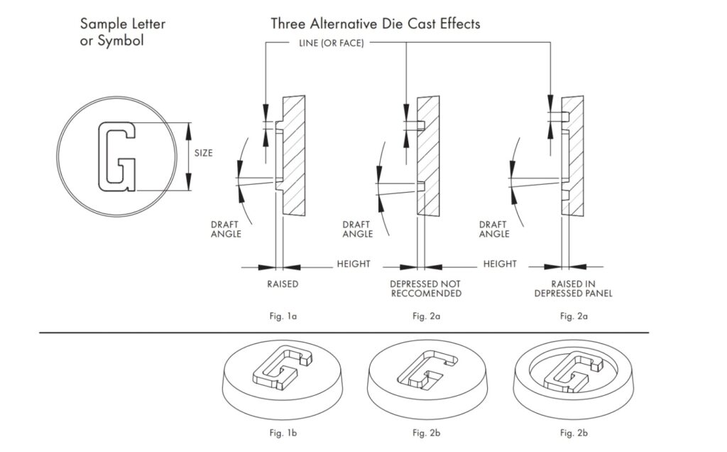
Among these three ways, the most economical one is to make the lettering as a raised feature. To achieve the raised feature in aluminum castings, a recessed feature needs to be made for the mold. This feature is easy to construct in the mold and causes minimal wear during operation. For the raised lettering (recessed in the mold), the mold has lower construction and maintenance costs during its service life.
On the contrary, recessed engraving in aluminum castings will result in raised features protruding into the mold. Its construction is somewhat complicated and requires more maintenance.
If designers want to maintain a flat surface, they can make the engraving as a raised feature within a recessed panel. This is more practical because you can apply recessed features without worrying about damaging the mold. Considering the coating that may be applied later, if you do not want a certain part to be filled by the coating, it is best to avoid unnecessary recesses in the design to prevent unnecessary filling effects after coating.
Additional guidelines
- The face (line thickness) of any letters or symbols should be at least 0.010 in. (0.254 mm) or larger.
- The height of casting lines or symbols should be equal to or less than their line thickness.
- Any engraving or decoration, including complex details or fine serifs, may not be clear during casting. Therefore, if possible, try to simplify them.
- The draft angle should not be less than 10°.
Following these guidelines should be helpful in most cases. If you have other requirements, you can always consult with your die casting manufacturer or Daye Diecasting for more targeted advice.